Transformer Oil Diagnostics
In addition to dissipating heat due to losses in a transformer, insulating oil provides a medium with high dielectric strength in which the coils and core are submerged. This allows the transformers to be more compact, which reduces costs. Insulating oil in good condition will withstand far more voltage across connections inside the transformer tank than will air. An arc would jump across the same spacing of internal energized components at a much lower voltage if the tank had only air. In addition, oil conducts heat away from energized components much better than air.
Over time, oil degrades from normal operations, due to heat and contaminants. Oil cannot retain high dielectric strength when exposed to air or moisture. Dielectric strength declines with absorption of moisture and oxygen. These contaminants also deteriorate the paper insulation. For this reason, efforts are made to prevent insulating oil from contacting air, especially on larger power transformers. Using a tightly sealed transformer tank is impractical, due to pressure variations resulting from thermal expansion and contraction of insulating oil. Common systems of sealing oil-filled transformers are the conservator with a flexible diaphragm or bladder or a positivepressure inert-gas (nitrogen) system. Reclamation GSU transformers are generally purchased with conservators, while smaller station service transformers have a pressurized nitrogen blanket on top of oil. Some station service transformers are dry-type, self-cooled or forcedair cooled.
Conservator System
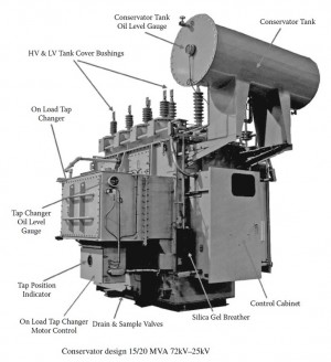
A conservator is connected by piping to the main transformer tank that is completely filled with oil. The conservator also is filled with oil and contains an expandable bladder or diaphragm between the oil and air to prevent air from contacting the oil. Figure 1 is a schematic representation of a conservator system (figure 1 is an actual photo of a conservator).

Figure 1: Conservator with Bladder
Air enters and exits the space above the bladder/diaphragm as the oil level in the main tank goes up and down with temperature. Air typically enters and exits through a desiccant-type air dryer that must have the desiccant replaced periodically. The main parts of the system are the expansion tank, bladder or diaphragm, breather, vent valves, liquid-level gauge and alarm switch. Vent valves are used to vent air from the system when filling the unit with oil. A liquid-level gauge indicates the need for adding or removing transformer oil to maintain the proper oil level and permit flexing of the diaphragm.
Oil-Filled, Inert-Gas System
A positive seal of the transformer oil may be provided by an inert-gas system. Here, the tank is slightly pressurized by an inert gas such as nitrogen. The main tank gas space above the oil is provided with a pressure gauge (figure 12. Since the entire system is designed to exclude air, it must operate with a positive pressure in the gas space above the oil; otherwise, air will be admitted in the event of a leak. Smaller station service units do not have nitrogen tanks attached to automatically add gas, and it is common practice to add nitrogen yearly each fall as the tank starts to draw partial vacuum, due to cooler weather. The excess gas is expelled each summer as loads and temperatures increase. Some systems are designed to add nitrogen automatically (figure 2) from pressurized tanks when the pressure drops below a set level. A positive pressure of approximately 0.5 to 5 pounds per square inch (psi) is maintained in the gas space above the oil to prevent ingress of air. This system includes a nitrogen gas cylinder; three-stage, pressure-reducing valve; high-and low-pressure gauges; high-and low-pressure alarm switch; an oil/condensate sump drain valve; an automatic pressure-relief valve; and necessary piping.

Figure 2: Typical Transformer Nitrogen System
The function of the three-stage, automatic pressure-reducing valves is to reduce the pressure of the nitrogen cylinder to supply the space above the oil at a maintained pressure of 0.5 to 5 psi. The high-pressure gauge normally has a range of 0 to 4,000 psi and indicates nitrogen cylinder pressure. The low-pressure gauge normally has a range of about -5 to +10 psi and indicates nitrogen pressure above the transformer oil. In some systems, the gauge is equipped with high- and low-pressure alarm switches to alarm when gas pressure reaches an abnormal value; the high-pressure gauge may be equipped with a pressure switch to sound an alarm when the supply cylinder pressure is running low. A sump and drain valve provide a means for collecting and removing condensate and oil from the gas. A pressure-relief valve opens and closes to release the gas from the transformer and, thus, limit the pressure in the transformer to a safe maximum value.
As temperature of a transformer rises, oil expands, and internal pressure increases, which may have to be relieved. When temperature drops, pressure drops, and nitrogen may have to be added, depending on the extent of the temperature change and pressure limits of the system.
.
Related articles


